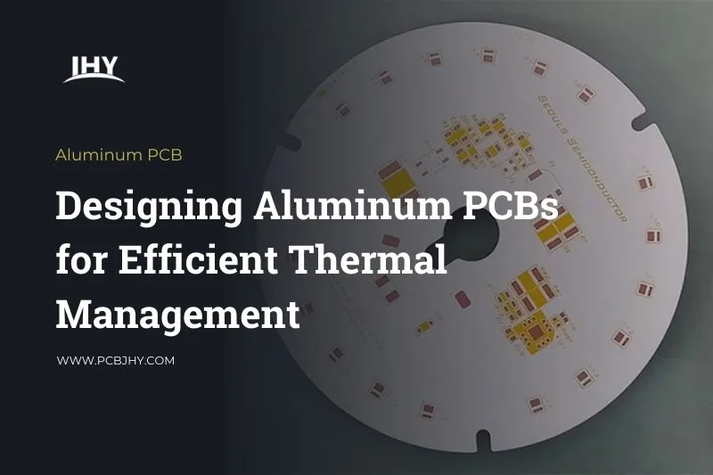
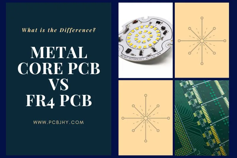
What is Metal Core PCB?
Metal Core PCB (MCPCB) is a type of printed circuit board that has a metal core as its base material instead of the traditional epoxy-glass or phenolic paper. The metal core provides superior thermal management capabilities, making it suitable for applications that generate high heat, such as power electronics and LED lighting. The metal core also provides a more stable and rigid base compared to traditional PCBs, making it suitable for applications that require high mechanical strength. MCPCBs are typically composed of a metal substrate, a thermally conductive dielectric layer, and a copper circuit layer. The metal substrate can be made of materials such as aluminum, copper, or steel, while the thermally conductive dielectric layer is usually made of materials such as ceramic or epoxy. The copper circuit layer is applied to the dielectric layer using various methods, such as plating or laminating.

Metal Core PCB Applications
MCPCBs are used in a wide range of applications that require superior thermal management capabilities. Here are some common applications of MCPCBs:
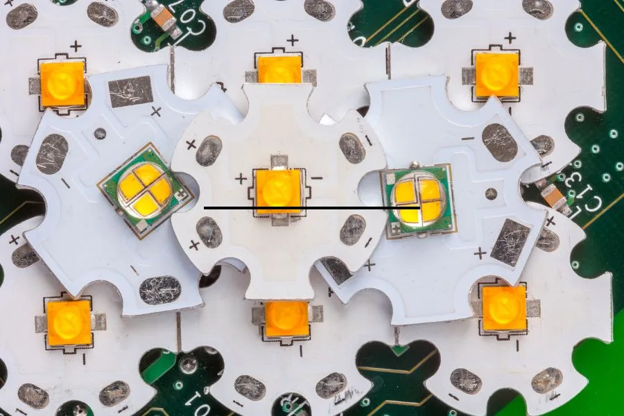
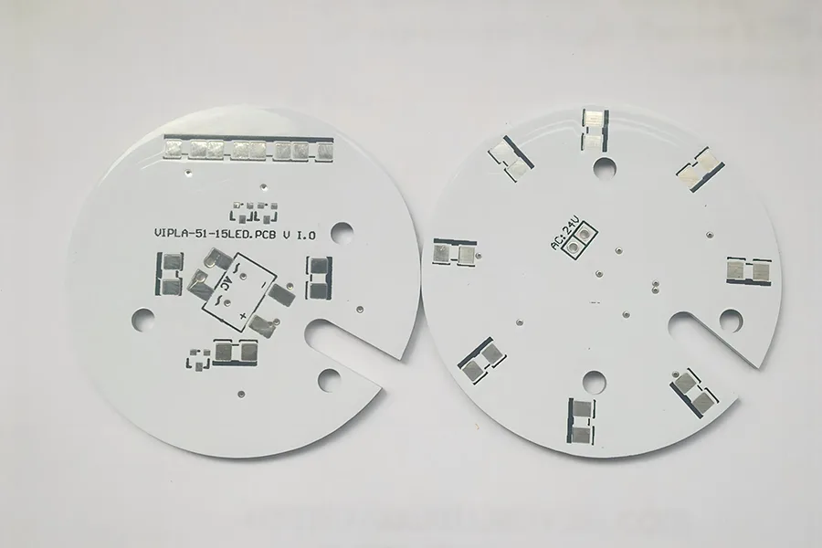
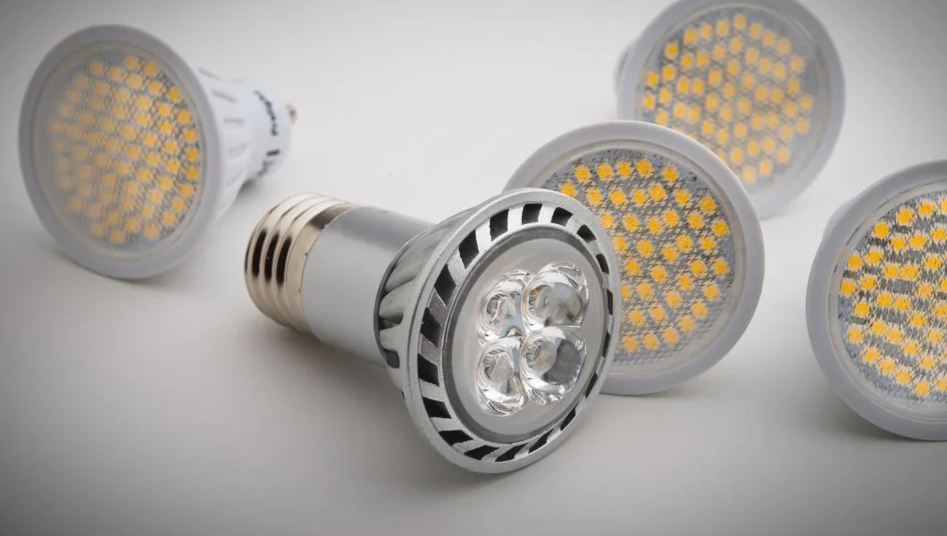
- LED Lighting:
MCPCBs are widely used in LED lighting applications due to their excellent heat dissipation properties. LED lighting fixtures generate a significant amount of heat, which can cause premature failure if not properly managed. MCPCBs help dissipate heat away from the LED chips, improving their lifespan and overall performance. - Power Electronics:
Power electronics, such as power supplies and inverters, generate high amounts of heat during operation. MCPCBs are used in these applications to manage the heat generated and prevent damage to components. MCPCBs also improve the reliability and lifespan of power electronic devices. - Automotive:
MCPCBs are used in the automotive industry for various applications, such as headlights, brake lights, and power modules. These applications require high thermal conductivity and mechanical strength, which MCPCBs can provide. - Aerospace:
Aerospace applications require PCBs that can withstand high temperatures and extreme environments. MCPCBs are used in aerospace applications such as avionics and communication systems due to their excellent thermal management capabilities and mechanical strength. - Medical:
Medical devices require high reliability and stability. MCPCBs are used in medical applications such as imaging equipment, surgical instruments, and monitoring devices to ensure high performance and reliability.
Advantages of Metal Core PCBs
- Thermal Management:
One of the primary advantages of MCPCBs is their superior thermal management capabilities. The metal core helps dissipate heat away from heat-generating components, improving their performance and lifespan. - Mechanical Strength:
MCPCBs have a more rigid and stable base compared to traditional PCBs, making them suitable for applications that require high mechanical strength. - Size and Weight:
MCPCBs can be designed to be thinner and lighter compared to traditional PCBs, making them suitable for applications where size and weight are critical. - Reliability:
MCPCBs have a higher resistance to thermal stress and mechanical shock compared to traditional PCBs, improving their overall reliability. - Higher Power Handling:
MCPCBs can handle higher power loads compared to traditional PCBs due to their improved thermal management capabilities.
Limitations of Metal Core PCBs
- Cost:
MCPCBs are generally more expensive than traditional PCBs due to the additional manufacturing steps and higher material costs. - Complexity:
The design and manufacturing of MCPCBs can be more complex compared to traditional PCBs due to the additional material layers and manufacturing processes. - Electrical Isolation:
The metal core in MCPCBs can sometimes interfere with electrical isolation between components, requiring additional isolation measures to be taken. - Manufacturing Limitations:
The selection of materials and manufacturing processes for MCPCBs can be limited compared to traditional PCBs, making it more difficult to find suitable manufacturers for some applications.
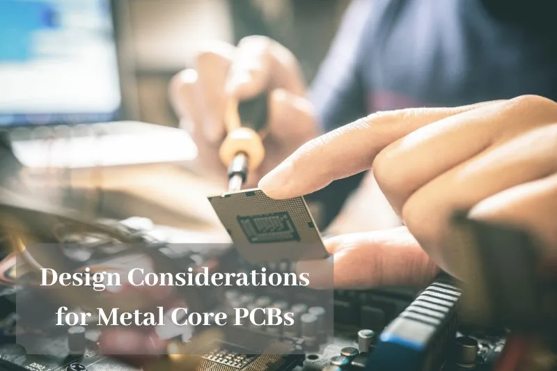
Design Considerations for Metal Core PCBs
Heat Dissipation
Heat dissipation is a critical consideration when designing Metal Core PCBs. Here are some important design considerations related to heat dissipation for MCPCBs:
- Thermal Conductivity:
The thermal conductivity of the metal core is one of the most important factors to consider when designing MCPCBs. The metal core should have a high thermal conductivity to efficiently transfer heat away from the heat-generating components to the surrounding environment. Aluminum is a common material used for MCPCBs due to its high thermal conductivity. - Heat Dissipation Area:
The size of the heat dissipation area is also an important consideration. The heat dissipation area should be large enough to effectively dissipate the heat generated by the components. This can be achieved by increasing the size of the metal core, or by adding additional heat dissipation features, such as thermal vias or thermal pads. - Heat Sink Design:
In addition to the metal core, additional heat sinks can be added to further improve heat dissipation. Heat sinks are designed to increase the surface area of the PCB, allowing more heat to be dissipated into the surrounding environment. Heat sinks can be designed in various shapes and sizes, depending on the specific application.
Material Selection
When designing a Metal Core PCB, the selection of materials is another important consideration. Here are some factors to consider when selecting materials for an MCPCB:
- Substrate Material:
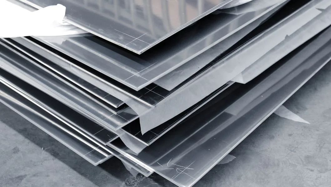
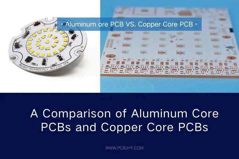
The substrate material is the insulating layer between the metal core and the copper layers. The substrate material should have high thermal resistance to minimize heat transfer from the metal core to the copper layers. Common substrate materials used for MCPCBs include fiberglass, ceramic, and polyimide. - Metal Core Material:
The metal core is the layer that provides the thermal conductivity for the PCB. Aluminum is a common metal core material used in MCPCBs due to its high thermal conductivity and relatively low cost. Copper and brass are also used, but they are more expensive. - Solder Mask:
The solder mask is the layer that covers the copper traces to prevent solder from flowing where it is not supposed to during assembly. The solder mask should be thermally conductive to improve heat dissipation. Some common thermally conductive materials used for solder masks include epoxy and silicone. - Solder Material:
The solder material used for MCPCBs should have good thermal conductivity to ensure that heat is efficiently transferred from the components to the metal core. Silver-based solders are commonly used for MCPCBs due to their high thermal conductivity. - Pin Material:
The pins or leads of the components should also be considered when designing MCPCBs. The pins should be made of a material that is compatible with the solder material and should have good thermal conductivity. Copper, gold, and silver are commonly used for pins.
Circuit Layout
Trace routing is another critical factor to consider when designing a Metal Core PCB. The design of the traces must take into account the heat generated by the components and the need for efficient heat dissipation. Using wider traces and thicker copper layers can help to reduce the resistance of the traces and improve the overall efficiency of the circuit.
- Layer Stackup:
The layer stackup is the arrangement of the different layers of the PCB. The number of layers and the arrangement of the layers can have a significant impact on the performance of the circuit. When designing an MCPCB, it is important to consider the layer stackup to ensure that the heat generated by the components can be efficiently dissipated. - Signal Traces:
The signal traces are the paths that carry the signals between the different components on the PCB. The signal traces should be placed in such a way that they are not affected by the heat generated by the components. It is important to avoid placing the signal traces near components that generate a lot of heat, such as power transistors or voltage regulators. - Power Traces:
The power traces are the paths that carry power to the different components on the PCB. The power traces should be designed to minimize resistance and inductance, which can cause voltage drops and noise. It is important to avoid placing the power traces near the signal traces, as this can cause electromagnetic interference. - Ground Planes:
The ground planes are the layers that provide a low-impedance path for the return current. It is important to have a good ground plane layout to minimize noise and provide a stable reference voltage. When designing an MCPCB, it is important to ensure that the ground plane is properly connected to the metal core to facilitate heat dissipation. - Component Placement:
The placement of the components on the PCB can have a significant impact on the performance of the circuit. When designing an MCPCB, it is important to place components that generate a lot of heat, such as power transistors, in locations where they can be efficiently cooled by the metal core.
Soldering Process
The soldering process is critical in manufacturing MCPCBs. The proper temperature, time, and method of soldering should be used to ensure a high-quality assembly.
- Solder Temperature:
The temperature of the soldering process is an important consideration in the design of an MCPCB. The metal core of the PCB has a high thermal conductivity, which means that it can dissipate heat very quickly. Therefore, it is important to use a soldering temperature that is high enough to ensure good soldering quality, but not so high that it damages the components or the PCB itself. - Soldering Time:
The duration of the soldering process is another important factor to consider. When the soldering time is too long, it can cause the components to be overheated, leading to damage or failure. On the other hand, if the soldering time is too short, it can result in poor soldering quality and insufficient bonding strength. - Soldering Method:
The method of soldering can also impact the design of an MCPCB. There are several methods for soldering, including reflow soldering and wave soldering. Reflow soldering is a popular method for soldering MCPCBs as it can provide consistent and precise soldering quality. Wave soldering, on the other hand, can be used for large-scale production but may not be suitable for MCPCBs with heat-generating components that require careful heat dissipation. - Soldering Alloy:
The choice of soldering alloy is also an important consideration in the design of an MCPCB. The most commonly used solder alloys are lead-free solders, which are preferred due to their lower environmental impact. However, lead-free solders have a higher melting point than traditional lead-based solders, which can make the soldering process more challenging. - Soldering Pads:
The design of the soldering pads is also an important consideration in the design of an MCPCB. The size and shape of the pads can impact the quality of the solder joint, so it is important to design the pads to ensure good solderability and to minimize the risk of solder bridging or insufficient wetting.
Related Reading