Effective thermal management has become a critical requirement in modern high-power electronics design. With power densities routinely exceeding 100W/inch^2, excessive heat buildup can severely degrade performance, reliability and even lead to catastrophic failures if not properly dissipated. Traditional FR4 PCBs often struggle to provide sufficient cooling for devices like high-brightness LEDs, RF power amplifiers, automotive electronics, and aerospace systems operating under extreme thermal loads.
Aluminum PCBs offer a high-performance solution by utilizing the exceptional thermal conductivity of aluminum – over 200W/m·K – nearly 50 times higher than FR4’s 0.25W/m·K. These specialized boards seamlessly integrate a highly conductive aluminum base layer with an insulating dielectric layer and circuitry, enabling efficient heat extraction and dissipation over the entire surface area.
With their superior thermal capabilities, aluminum PCBs can reduce junction temperatures by 20-30°C compared to conventional FR4 PCB boards under the same conditions. Their low thermal resistance in the range of 0.05-0.2K/W allows highly effective cooling of high power devices like 10W+ LEDs. This unmatched heat dissipation enables higher operating power, smaller form factors, and increased product lifespans.
As electronics continue pushing performance envelopes, aluminum printed circuit boards have become an essential thermal management solution across diverse industries. From high-intensity LED lighting and 5G infrastructure to aerospace/defense systems and industrial automation, these specialized PCBs ensure reliable operation even under the most demanding environmental conditions.
Understanding Aluminum PCB Basics
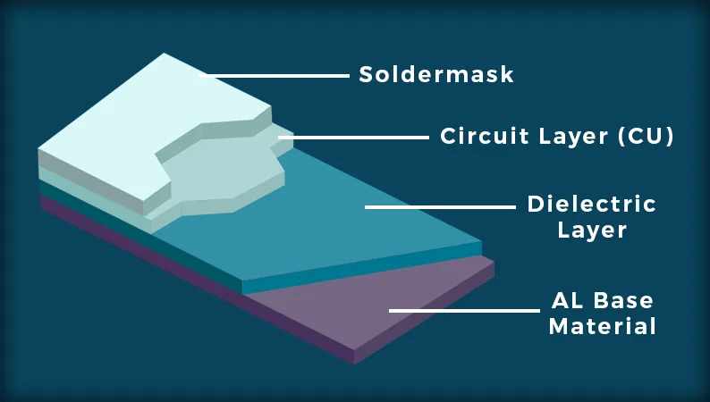
Aluminum PCBs have a unique multilayer construction designed to combine excellent thermal performance with electrical insulation and circuitry integration. They consist of three key layers:
The Metal Base Layer
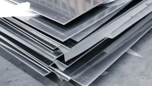
The foundation is a thick aluminum substrate, typically made from high thermal conductivity aluminum alloys like 6061 or 5052. This metal base provides the exceptional heat spreading and dissipation capabilities that make aluminum PCBs so effective for thermal management.
The Insulating Layer
Separating the metal base from the circuitry is a thin dielectric insulating layer. This is typically made from thermally conductive but electrically insulating materials like aluminum nitride (AlN) or alumina (Al2O3). It allows efficient heat transfer from the components to the aluminum base while preventing electrical shorts.
The Circuit Layer
On top of the insulating layer is the copper foil circuitry layer where the traces, pads and components are mounted, similar to conventional PCBs. This layer can have multiple levels of routing artfully integrated with the thermally optimized aluminum base.
During manufacturing, the insulating layer is either directly bonded to the aluminum base through thermal processes or an additional adhesive layer is utilized. A thin oxide coating forms on the exposed aluminum surfaces, further enhancing electrical isolation.
This unique aluminum PCB stack-up provides a combination of unparalleled thermal conductivity from the metal base, robust electrical insulation, and the ability to incorporate high-density interconnects – making it the ideal solution for dissipating heat in high-power applications.
Benefits of Using Aluminum PCBs
Aluminum printed circuit boards provide several game-changing benefits when it comes to thermal management and heat dissipation for high-power electronics:
- Unmatched Thermal Conductivity
The key advantage of aluminum PCBs lies in the superior thermal conductivity of aluminum itself – around 200W/m·K. This is a staggering 50 times higher than standard FR4’s conductivity of only 0.25W/m·K. Such high thermal conductivity allows the aluminum base to rapidly pull heat away from hot components and spread it across the entire board area for efficient dissipation. - Dramatically Lower Operating Temperatures
This unmatched heat transfer capability directly translates into significantly reduced operating temperatures for components mounted on aluminum PCBs. Real-world testing data shows junction temperature reductions of 20°C to 30°C compared to identical components on FR4 boards under the same conditions. Lower temperatures increase product reliability and lifetime. - Higher Power Handling Capacity
By maintaining lower operating temperatures, aluminum PCBs enable much higher power handling capacities. For example, high-brightness LED arrays can easily exceed 10W per LED while still remaining within safe thermal limits when mounted on an aluminum PCB. This allows for higher light output, smaller form factors, and increased lumen/area density. - Minimized Thermal Resistance
The multi-layer construction of aluminum PCBs results in extremely low overall thermal resistance values in the range of 0.05 – 0.2 K/W. This ensures very efficient heat extraction from components through the insulating layer to the thermally conductive aluminum base below. Minimal thermal bottlenecks maximize cooling performance. - Low Weight
yet Durable While offering superior thermal performance, aluminum PCBs are also more lightweight than conventional FR4 boards. The high strength-to-weight ratio of aluminum allows for rugged mechanical designs. This makes aluminum PCBs ideal for weight-critical applications like aerospace and automotive electronics that must also withstand vibrations and shocks.
With their exceptional thermal capabilities, low impedances, light weight yet durability – aluminum printed circuit boards outperform conventional FR4 PCBs in virtually every thermal management aspect for high-power applications. Their advantages enable new frontiers in product design and reliability.
Key Considerations in Aluminum PCB Design
Thermal Design Considerations
To fully leverage the superior heat dissipation capabilities of aluminum PCBs, there are several critical thermal design aspects that must be carefully considered:
- Power Mapping and Thermal Modeling
The first step is to estimate the power dissipation levels of all components on the board to map out potential hot spots. This thermal load analysis helps determine if a standard or higher conductivity aluminum base is required. Computational tools like finite element analysis (FEA) and computational fluid dynamics (CFD) software can then accurately model heat transfer and airflow to optimize the PCB design. - Trace Width and Routing
For high current paths on the board, trace widths must be sized appropriately to minimize resistive heating from I2R losses. Using thick copper weights and spreading power planes can further reduce heating from trace runs. Careful routing to minimize loop inductances also cuts down AC losses at high frequencies. - Thermal Via Utilization
Thermal vias provide a low-resistance vertical conduction path from hot components on the surface, through the insulating dielectric, directly into the aluminum base below. Strategically placing these vias in high-power areas ensures efficient heat extraction into the spreader plane. - Stack-Up Optimization
The layer stack sequence in aluminum PCBs also influences thermal performance. Using highly conductive aluminum core layers close to the heat sources maximizes heat transfer. The dielectric material’s thermal properties and minimizing its thickness are also critical considerations. - Airflow and Heat Sinking
While aluminum PCBs excel at spreading heat, that heat must still be removed from the board’s surfaces through conduction, convection or radiation. Proper openings for airflow, fan placement, and integrating additional heat sinks all enhance the PCB’s overall cooling capabilities.
By combining comprehensive thermal analysis, optimized PCB layouts, strategic thermal via placement, customized stack-up profiles and effective heat sinking – designers can fully extract the maximum thermal performance from aluminum printed circuit boards. Careful thermal design prevents hot spots and ensures reliable operation even for the most demanding high-power applications.
Optimized Component Placement and Layout
Component placement and overall PCB layout play a crucial role in maximizing heat dissipation from an aluminum board:
- Hot-Spot Management: High power components like FPGAs, processors and power ICs should be spaced out instead of clustered together to avoid concentrated hot spots.
- Thermal Interfacing: These heat-generating devices should be positioned to have maximum thermal interfacing with the aluminum base – either through direct contact or strategically placed thermal vias.
- Convection Cooling: Lower power but temperature-sensitive components like sensors and RF ICs should be oriented perpendicular to the airflow direction for efficient convection cooling.
- Exposing Metal Areas: Large aluminum plane areas should be strategically exposed to the airflow path to act as heat sinking surfaces for heat radiation.
- Component Orientation: Orienting tall components parallel to airflow minimizes turbulence and stagnation that could increase hot spot formation.
By balancing thermal and electromagnetic considerations during the layout process, an optimized aluminum PCB design can ensure reliable operation even under extreme temperature conditions. Thermal modeling is recommended to validate layout heat transfer performance.
Aluminum PCB Design Tools and Techniques
A. PCB Design Software
Several PCB design software tools available on the market can be used to design aluminum PCBs. Some popular options include Altium Designer, Eagle PCB, and KiCAD. These tools offer a range of features, including schematic capture, layout tools, and design rule checking.
B. Thermal Simulation Software
In addition to PCB design software, thermal simulation software can also be used to optimize the thermal performance of aluminum PCBs. These tools allow designers to simulate the thermal behavior of the board and identify potential hot spots and thermal issues before the board is manufactured.
Some popular thermal simulation software tools include ANSYS Icepak, SolidWorks Flow Simulation, and SimScale.
C. Design Guidelines and Best Practices
Several design guidelines and best practices can be followed to optimize the design of aluminum PCBs. These include:
- Minimize the thermal resistance of the board by using a substrate with high thermal conductivity, minimizing the thickness of the insulation layer, and minimizing the number and size of vias.
- Use thermal vias to connect the component pads to the metal substrate or place the components in direct contact with the metal substrate.
- Minimize the length and width of the traces to reduce resistance and heat generation.
- Place the components in a way that avoids hot spots and maximizes thermal contact with the substrate.
- Use thermal simulation software to identify potential hot spots and optimize the design.
Case Studies
To illustrate the design process of aluminum PCBs, here are two case studies:
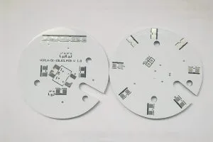
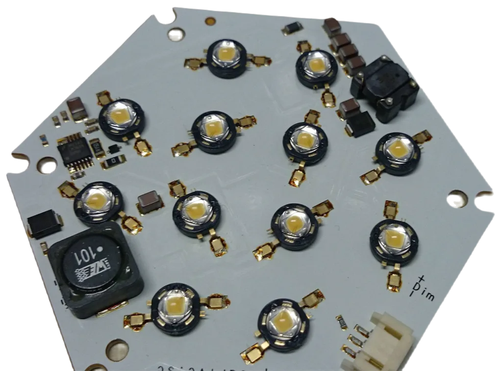
Case Study 1: High-Power LED Lighting
A manufacturer of high-power LED lighting products needed an aluminum PCB design that could handle high power and dissipate heat efficiently. The design team used ANSYS Icepak to simulate the thermal behavior of the board and optimize the layer stack and layout.
The final design featured a 1.6mm thick aluminum substrate with a 2 oz copper layer, a thin insulation layer, and a component layout that maximized thermal contact with the substrate. The design also featured thermal vias that connected the component pads to the substrate, minimizing the thermal resistance of the board.
Case Study 2: Power Supply
A power supply designer needed an aluminum PCB design that could handle high power and voltage while also providing efficient heat dissipation. The design team used SolidWorks Flow Simulation to simulate the thermal behavior of the board and optimize the layer stack and layout.
The final design featured a 2mm thick aluminum substrate with a 3 oz copper layer, a thin insulation layer, and a component layout that minimized the thermal resistance of the board. The design also featured thermal vias and direct contact between the components and the substrate, maximizing thermal contact and minimizing hot spots.
Applications and Examples
The exceptional thermal capabilities of aluminum PCBs have made them invaluable across a diverse range of applications where effective heat dissipation is critical for reliable operation. Here are some key examples:
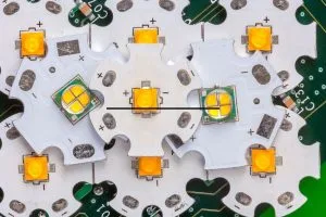
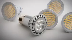
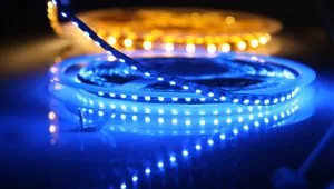
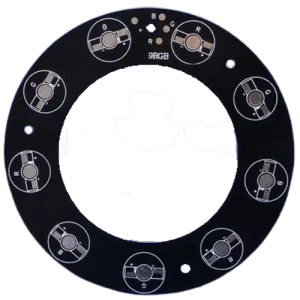
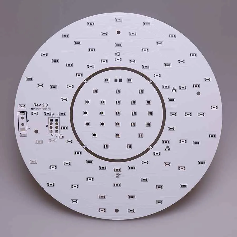
- LED Lighting Systems
High-brightness LED arrays can generate enormous amounts of heat, with thermal loads exceeding 50W for a single high-power LED. Aluminum PCBs allow these LEDs to be driven at higher currents, enabling higher light output and lumen density. Leading LED lighting manufacturers like Cree and Ledil utilize aluminum PCBs to build ultra-bright yet compact lamps and luminaires. - RF Power Amplifiers
The high frequencies and watt-level output powers involved in RF power amplifiers result in significant heat generation. Aluminum PCBs provide the vital heat extraction needed for devices like GaN HEMTs/MMICs used in 5G infrastructure, avionics, and satellite communications. Major OEMs like Skyworks rely on aluminum PCBs for their high-power RF products. - Automotive Electronics
The harsh under-hood environments of automotive electronics demand rugged, high-reliability thermal solutions. From engine control units and battery monitoring modules to RADAR/LIDAR sensors, aluminum PCBs enable compact form factors while ensuring reliable operation across extreme temperatures. - Telecom Infrastructure
As 5G deployments gather steam, the shift toward compact massive MIMO antennas has further increased thermal challenges. Aluminum PCBs are being leveraged in remote radio units and baseband units to cool high-power transmitters, receivers and Digital Signal Processors handling multi-Gbps bandwidths. - Industrial Laser Systems
High-power industrial lasers like those used for materials processing necessitate effective heat sinks for electro-optic components. The low thermal resistance and heat spreading ability of aluminum PCBs make them well-suited for thermally managing laser diode arrays and drive electronics.
In addition to these examples, aluminum PCBs are also finding increasing adoption in industrial automation equipment, aerospace/defense systems, test/measurement gear and more – anywhere power density and thermal reliability are paramount.
As electronics continue pushing performance envelopes, the thermal management benefits of aluminum printed circuit boards will only become more vital across industries. Their ability to keep temperature rises in check enables cutting-edge electronics to deliver their full potential.
Conclusion
As electronics continue pushing the boundaries of performance and miniaturization, effective thermal management has become a make-or-break requirement. Traditional FR4 PCBs often struggle to dissipate heat from today’s compact, high-power devices.
Aluminum printed circuit boards provide a superior thermal solution by leveraging aluminum’s exceptional 200W/m·K thermal conductivity – enabling high heat spreading and efficient cooling. Their optimized multilayer construction combines a thermally conductive aluminum base with an insulating dielectric layer, allowing high power components to operate reliably within safe temperature limits.
Looking ahead, the adoption of advanced packaging, wide-bandgap semiconductors and heterogeneous integration will further elevate power densities. This makes the superior thermal capabilities of aluminum PCBs absolutely vital across sectors like power electronics, RF/5G infrastructure, industrial automation and more.
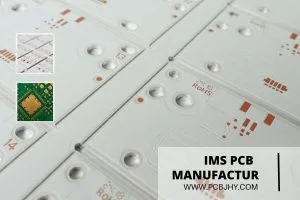
At JHYPCB, we specialize in manufacturing high-quality aluminum PCBs leveraging decades of thermal management expertise. Our state-of-the-art facilities provide rapid aluminum PCB prototype services along with volume production, delivering unmatched thermal performance from design to deployment.
Contact us today to learn how our aluminum PCB solutions can give your high-power products a thermal edge while meeting stringent reliability standards. With JHYPCB, bring your most thermally challenging designs to market with confidence.
Related Reading