Introduction
In the rapidly evolving world of electronics, thermal management has become a critical challenge. As devices become smaller, more powerful, and more densely packed, the need for effective heat dissipation has never been greater. This is where Insulated Metal Substrate (IMS) PCBs come into play, offering a revolutionary solution to the thermal constraints of traditional PCB technologies.
IMS PCBs, also known as metal core PCBs or metal base PCBs, represent a significant leap forward in printed circuit board design. By incorporating a metal substrate—typically aluminum or copper—these innovative boards provide unparalleled thermal conductivity, allowing for efficient heat dissipation in high-power applications.
In this comprehensive guide, we’ll delve deep into the world of IMS PCBs. We’ll explore their unique structure, the materials used in their construction, and the myriad benefits they offer over traditional FR-4 PCBs. From LED lighting to automotive electronics, we’ll examine the wide range of applications where IMS PCBs are making a significant impact.
Whether you’re an engineer seeking solutions for thermal management challenges, a product designer looking to optimize your next project, or simply curious about the latest advancements in PCB technology, this article will provide you with valuable insights into the world of Insulated Metal Substrate PCBs.
Join us as we unravel the complexities of IMS PCB technology and discover how these innovative boards are shaping the future of electronics design.
What is IMS PCB?
IMS PCB stands for insulated metal substrate printed circuit board. As the name suggests, these boards use a metal base layer as the foundation instead of the typical laminate materials like FR-4. This metal core gives IMS PCBs their distinctive properties and performance advantages.
An IMS PCB is also referred to as:
- Metal core PCB
- Metal base PCB
- Thermally conductive PCB
- Thermal PCB board
The metal used for the core substrate is typically aluminum or copper due to their high thermal conductivity. However, other metals can also be used depending on the design requirements.
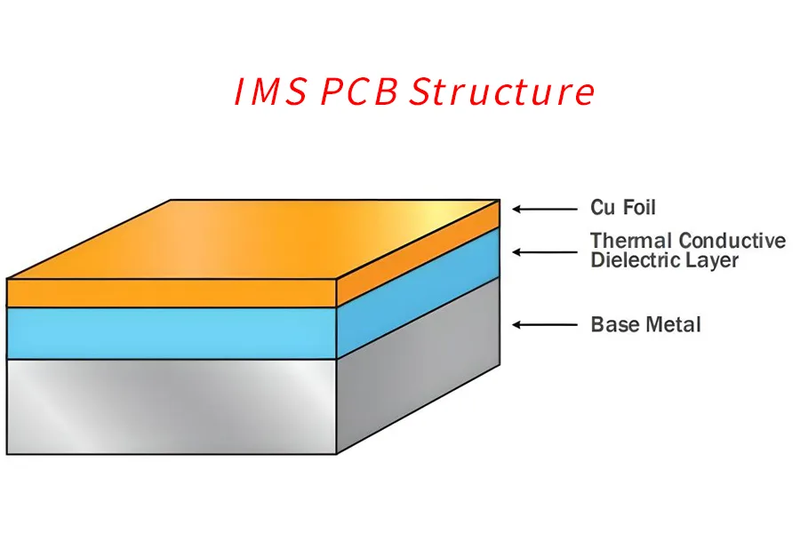
The planar metal layer provides the underlying support structure for the PCB. It is then laminated with dielectric insulation layers on top and bottom. These thermally conductive dielectric layers electrically isolate the metal substrate. Common materials used include epoxy, polyimide, PET, and PEN.
On top of the dielectric layers, copper sheets are laminated to create the traces, pads, vias, and other conductive features required for the circuit board. This is similar to the layer stack-up used for conventional PCB fabrication.
The end result is a circuit board capable of conducting heat 400-1000 times better than standard FR-4 boards. This enables IMS PCBs to dissipate heat extremely effectively from heat-generating components.
IMS PCB Structure and Materials
The unique properties of IMS PCBs stem from their layered construction, which typically consists of three main components:
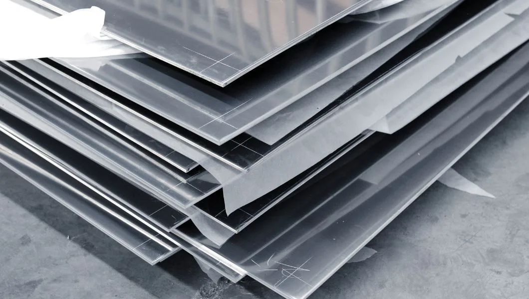
1. Metal Core Substrate
- Function: Forms the base of the PCB, providing mechanical support and heat dissipation.
- Common Materials:
- Aluminum (1xxx, 5xxx, 6xxx series)
- Copper
- Thickness: Typically ranges from 0.5mm to 3mm
- Properties:
- High thermal conductivity (Aluminum: ~180 W/m·K, Copper: ~400 W/m·K)
- Excellent mechanical strength
- Good workability
2. Dielectric Insulation Layer
- Function: Electrically isolates the metal substrate from the copper circuit layer while allowing heat transfer.
- Common Materials:
- <>Epoxy-based compounds
- Polyimide
- Ceramic-filled polymers
- Thickness: Usually between 50μm to 200μm
- Key Properties:
- Thermal conductivity: 1-7 W/m·K (much higher than FR-4’s ~0.3 W/m·K)
- High electrical insulation (breakdown voltage >3kV)
- Low thermal expansion coefficient
- Strong adhesion to both metal and copper
3. Copper Circuit Layer
- Function: Carries the electrical signals and forms the circuit pattern.
- Thickness: Typically 35μm to 210μm (1oz to 6oz copper weight)
- Application Methods:
- Laminated copper foil
- Electrodeposited copper
Additional Layers and Finishes
- Solder Mask: Applied over the copper layer for protection and insulation
- Surface Finish: Options include HASL, ENIG, Immersion Tin, OSP
- Silkscreen: For component markings and identifications
Material Selection Considerations
- Thermal Requirements: The choice of materials significantly affects the overall thermal performance.
- Mechanical Needs: Consider factors like CTE (Coefficient of Thermal Expansion) matching to prevent warpage.
- Electrical Performance: Dielectric properties affect signal integrity, especially at high frequencies.
- Cost Constraints: Balance between performance and budget, with aluminum generally being more cost-effective than copper.
- Environmental Factors: Consider operating temperature range and potential exposure to harsh conditions.
By carefully selecting and engineering these materials, IMS PCBs achieve their superior thermal management capabilities while maintaining excellent electrical performance. This makes them ideal for applications where heat dissipation is crucial, such as high-power LEDs, motor drives, and power converters.
Benefits of IMS PCBs
IMS PCBs provide several advantages that make them an attractive option for many electronics applications:
- Thermal Performance
The metal core substrate allows heat to spread out and dissipate rapidly. This gives IMS PCBs 400-1000 times better thermal conductivity than standard FR-4 boards. Components stay cooler, and thermal management is easier.
- Heat Dissipation
The heat-spreading capability enables heat-generating components to be placed more densely. Heat flows into the metal base and away from critical devices. This supports advanced thermal management.
- Thin and Lightweight
With a high-strength metal foundation, IMS PCBs can be fabricated thinner than typical PCBs. This allows more compact, space-saving designs. Less dielectric material also reduces weight.
- Vibration and Shock Resistance
The metal substrate provides enhanced structural rigidity. IMS PCBs resist flexing, vibration, and shock better than normal PCBs.
- Design Flexibility
IMS technology supports complex board shapes, internal cutouts, and integrated metal heat sinks. This facilitates innovative cooling strategies.
In summary, the combination of cooling capacity, lightweight, and robustness make IMS PCBs ideal for many demanding applications. Their high thermal conductivity unlocks performance potential not achievable with standard PCB materials.
IMS PCB Classifications
There are a few ways that insulated metal substrate PCBs can be categorized based on their core metal and layer stackup:
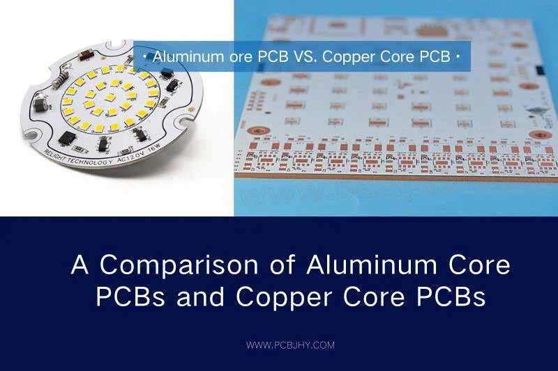
- Core Metal – Aluminum IMS PCB, Copper IMS PCB, Stainless Steel IMS PCB. Copper offers the best thermal conductivity.
- Layer Count – Single layer IMS PCB, Double layer IMS PCB, Multilayer IMS PCB with 4, 6, 8, etc layers. More layers allow complex routing.
- Board Thickness – Varies based on layer count. Typical range is 0.8mm to 3mm thick.
- Circuit Type – Single-sided, double-sided, or multilayer circuit layouts. Double-sided is very common.
- Board Shape – Standard rectangle or custom shapes with complex contours and cutouts.
Key factors in selecting the IMS PCB type are the thermal and mechanical requirements, circuit complexity, and application constraints like weight and space. Consulting an expert IMS PCB manufacturer is recommended to determine the optimal IMS board specifications.

IMS PCB Applications
The unmatched thermal performance of IMS PCBs makes them well-suited for applications that require effective heat dissipation from sensitive electronics. Some of the leading uses of insulated metal substrate PCBs include:
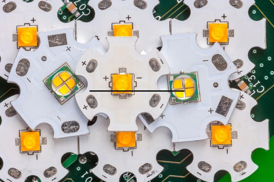
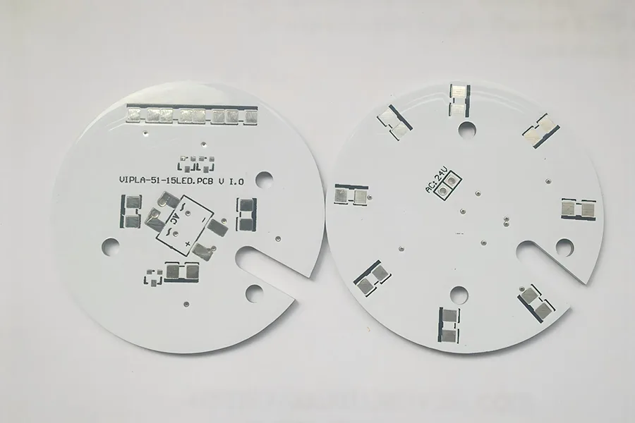
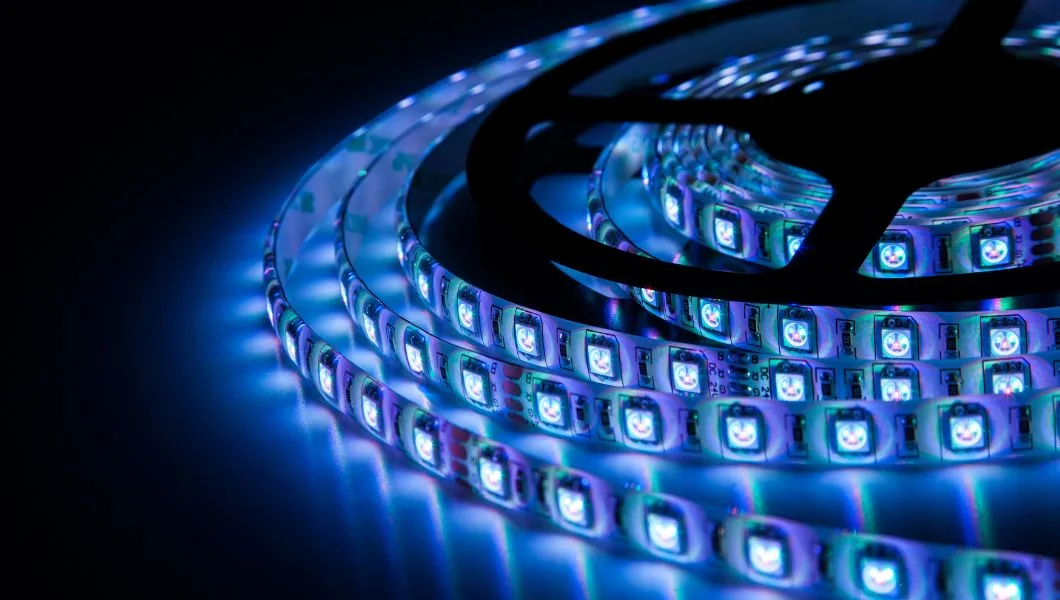
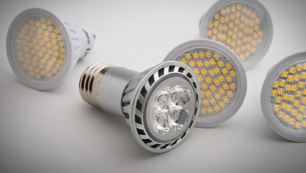
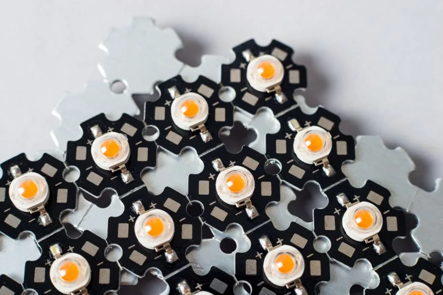
- LED Lighting – The high-power LEDs used in lighting generate significant heat. IMS PCBs dissipate the heat to maintain light output and lifespan.
- Power Electronics – IGBTs, power converters, and other power devices benefit from the cooling capacity of IMS PCBs.
- Automotive – The high ambient temperatures in automotive environments make cooling essential for engine control units, infotainment, and ADAS.
- Aerospace/Aviation – Cooling electronics in cramped, high-altitude environments is critical. IMS offers thermal stability for avionics.
- 5G Telecom – Dense 5G radio components need cooling as data rates increase. IMS allows packing of more components.
- Consumer Devices – From phones to game consoles, IMS PCBs help cool compact mobile consumer electronics.
- Medical – Analytical devices like PCR thermocyclers require precise thermal control that IMS provides.
The above represents the industries where insulated metal substrate PCBs are most widely adopted currently. With continuing technological advances, IMS technology has the potential to expand into additional applications in the future.
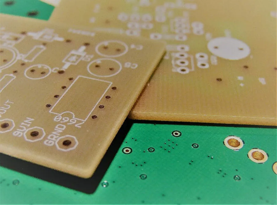
IMS PCB vs FR-4 PCB
There are several key differences between IMS PCBs and standard FR-4 PCBs:
- Thermal Conductivity – The metal core of IMS PCBs provides 400-1000X higher thermal conductivity than FR-4.
- Heat Dissipation – The metal foundation allows rapid spreading and dissipation of heat vs the insulative FR-4 material.
- Structural Rigidity – IMS PCBs are stronger and resist flexion and vibration better than FR-4.
- Weight – IMS PCBs can be fabricated thinner and lighter than FR-4 thanks to the metal layer.
- Dielectric Material – FR-4 uses glass-reinforced epoxy. IMS PCBs use thermally conductive polymers.
- Cost – IMS PCBs have a higher material cost due to the metal substrate and dielectric.
- Applications – IMS is better suited for the thermal management of power electronics, while FR-4 works for less demanding applications.
In summary, IMS PCBs provide superior cooling capacity and ruggedness compared to standard FR-4 PCBs. Their thermal and mechanical performance makes IMS the ideal choice for heat-sensitive electronics.
IMS PCB vs FR-4 PCB: A Comprehensive Comparison
| Feature | IMS PCB | FR-4 PCB |
|---|---|---|
| Base Material | Metal (usually aluminum or copper) | Glass-reinforced epoxy laminate |
| Thermal Conductivity | 1-7 W/m·K (dielectric layer)<br>140-400 W/m·K (metal core) | ~0.3 W/m·K |
| Heat Dissipation | Excellent | Poor to moderate |
| Coefficient of Thermal Expansion (CTE) | Similar to mounted components (e.g., ~23 ppm/°C for aluminum core) | Higher than most components (~14-17 ppm/°C) |
| Thickness | Can be thinner due to metal core strength | Generally thicker for comparable strength |
| Weight | Can be lighter for the same strength | Heavier for comparable strength |
| Structural Rigidity | High | Moderate |
| Vibration Resistance | Excellent | Good |
| Multilayer Capability | Limited (typically 1-2 layers) | Excellent (can have many layers) |
| Cost | Higher | Lower |
| Typical Applications | High-power LEDs, power electronics, automotive, aerospace | General electronics, consumer devices, low to medium power applications |
| Maximum Operating Temperature | Higher (up to 150°C or more) | Lower (typically up to 130°C) |
| Electrical Insulation | Good (depends on dielectric layer) | Excellent |
| Signal Integrity at High Frequencies | Can be challenging due to ground plane effect | Good |
| Ease of Manufacturing | More complex | Simpler |
| Repairability | More difficult | Easier |
| Environmental Impact | Potentially better due to longer lifespan of components | Standard |
IMS PCB Manufacturing Process
IMS PCB fabrication utilizes many of the same techniques as standard PCB manufacturing. However, additional steps are required to bond the metal and dielectric layers properly. Here is an overview of the IMS board fabrication process:
- PCB Prototyping – The manufacturing process begins with PCB milling or CNC machining for prototype boards. This allows testing design concepts and thermal performance.
- Metal Etching – The core metal substrate must be etched to create cutouts, cavities, and other features. Photolithography and chemical etching are typically used.
- Surface Treatment – The metal uses chemical and mechanical processes to improve adhesion. Common pre-treatments include cleaning, abrasion, and oxide removal.
- Dielectric Layer Lamination – Using high heat and pressure, the dielectric material is laminated onto the treated metal core. Multiple layers can be added.
- Copper Layer Bonding – Copper foils are bonded to the dielectric layers to create the conductive layers for traces and vias.
- PCB Imaging – Photoresist is applied, and the board is imaged to transfer the circuit pattern using lithography processes.
- Copper Etching – Unwanted copper is removed through etching to leave only the desired conductor pattern on the PCB.
- Plating and Coating – Platings like ENIG or HASL are applied to protect the copper and facilitate soldering.
- Drilling and Routing – Holes are mechanically drilled and routed to create vias and cut board contours.
- Final Testing – Electrical testing and quality inspection complete the manufacturing process before shipping.
The specialized materials and fabrication of insulated metal substrate PCBs require technical expertise. Working with an experienced IMS PCB manufacturer helps ensure optimal results.
JHYPCB - Your IMS PCB Manufacturer
As an IMS PCB manufacturer, JHYPCB provides high-quality metal core, metal base PCB prototyping and production services. With advanced manufacturing capabilities and expertise, JHYPCB is a leader in insulated metal substrate PCB technology.
JHYPCB’s capability and technical specification
- 10+ years focused on IMS PCB fabrication
- Volume production capacity up to 1,000 pieces per day
- Minimum feature size down to 3mil line/space
- Via sizes down to 0.2mm drilled hole
- Layer count up to 20 layers
- RoHS-compliant and UL-certified
- Complete quality testing and assurance
- Materials: Aluminium & copper plates. FR-4, PTFE, thermal dielectrics.
- Dielectric thickness: 0.05mm – 0.20mm
- Thermal conductivity: 1-12 W/m/K
- Profile method: Punching, Liquid cooled routing
- Copper weights (finished): 35μm – 140μm
- Minimum track and gaps: 0.10mm / 0.10mm
- Metal core thickness: 0.40mm – 3.20mm
- Maximum dimensions: 550mm x 700mm
- Surface finishes available: HASL, LF HASL, OSP, ENIG, Immersion tin, Immersion silver
- Minimum mechanical drill: 0.30mm
- Minimum laser drill: 0.10mm standard, 0.075mm advanced
JHYPCB has the technical knowledge and process controls to manufacture complex IMS boards cost-effectively. Whether you need a simple 2-layer IMS PCB prototype or multilayer metal core boards for volume production, JHYPCB can deliver quality and service.
Contact the JHYPCB team to discuss your next insulated metal substrate PCB project and learn more about our manufacturing capabilities.
FAQs about IMS PCBs
IMS PCB stands for Insulated Metal Substrate Printed Circuit Board. It's also known as a metal core PCB or metal base PCB.
The main difference is that IMS PCBs use a metal base (usually aluminum or copper) instead of the fiberglass base used in FR-4 PCBs. This gives IMS PCBs superior thermal conductivity, allowing for better heat dissipation.
The main advantages include:
- Excellent thermal management
- Higher power density
- Improved reliability in high-temperature environments
- Thinner and lighter designs
- Better resistance to vibration and shock
IMS PCBs are widely used in:
- LED lighting
- Power electronics
- Automotive electronics
- Aerospace and aviation
- 5G telecommunications
- High-performance computing
Generally, yes. The materials used in IMS PCBs are more expensive than those in standard PCBs. However, the improved performance and longevity often justify the higher cost in applications where thermal management is critical.
Yes, multilayer IMS PCBs are possible, although they are less common than single or double-layer designs due to the complexity of manufacturing.
The most common metals used are aluminum and copper. Aluminum is more cost-effective, while copper offers superior thermal conductivity.
IMS PCBs typically have a thermal conductivity 400-1000 times higher than standard FR-4 PCBs.
Yes, designers need to consider:
- Thermal management strategies
- CTE (Coefficient of Thermal Expansion) matching
- Dielectric strength requirements
- Potential limitations in via density
Rework and repair can be more challenging with IMS PCBs due to the metal core. It's possible, but requires specialized equipment and expertise.
Yes, IMS PCBs can contribute to energy efficiency in electronic systems by improving heat dissipation, potentially leading to longer product lifespans and reduced electronic waste.
The choice depends on your specific application. Aluminum is more cost-effective and lighter, making it suitable for many LED and automotive applications. Copper offers superior thermal performance and is often chosen for high-power applications where maximum heat dissipation is crucial.