


Your Trusted Prototype PCB Manufacturing And Assembly Partner.
When you partner with us, we do everything to ensure your PCB manufacturing and assembly are completed on time to your specifications with the highest quality.
Leading manufacturer of PCB Fabrication and Assembly in China.
FPC Coverlay, also known as Cover Film or Solder Mask, is a thin protective layer that is applied to the surface of flexible printed circuits (FPC) to protect the circuitry and components from external contaminants such as dust, moisture, and chemicals. It is typically made of a heat-resistant polymer material such as polyimide (PI) or polyester (PET) film, with an adhesive layer that is applied to the FPC substrate during the manufacturing process.
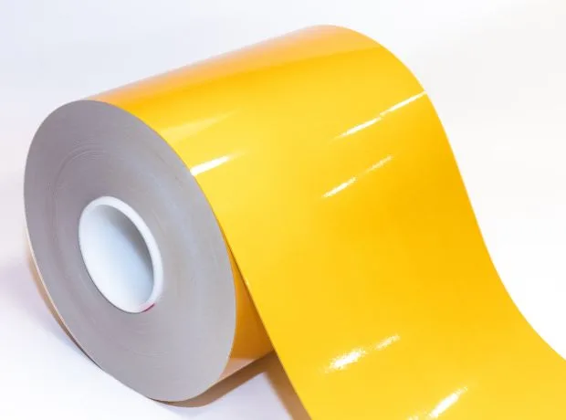
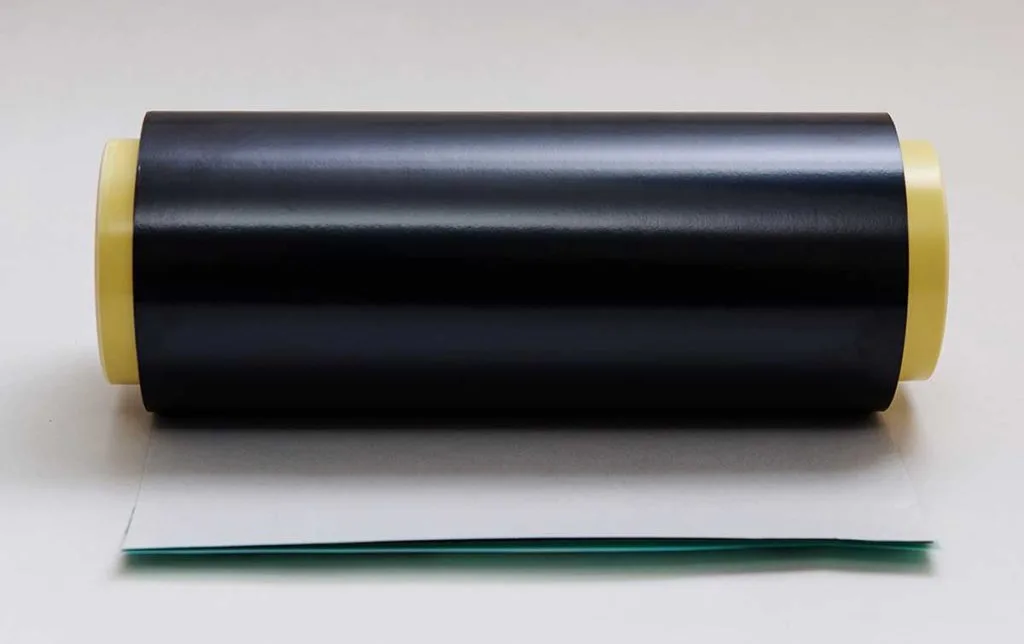
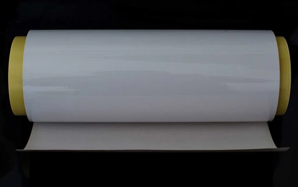
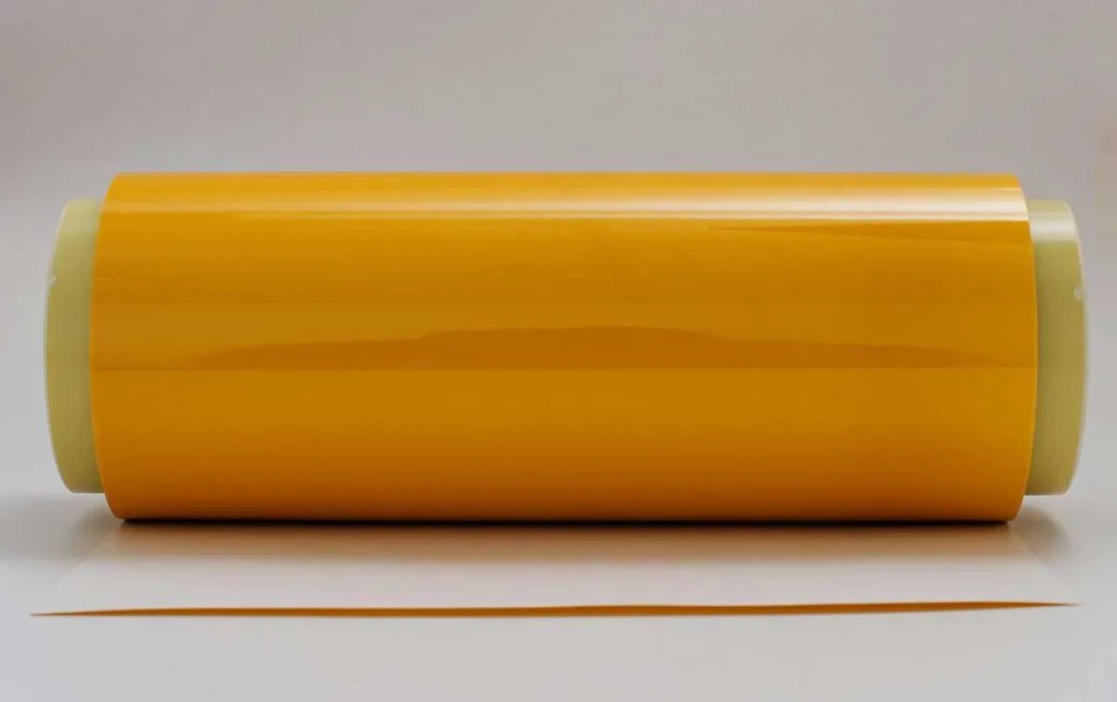
The colors for the coverlay of the flexible printed circuit board are yellow, white, and black.
FPC Coverlay plays a critical role in the manufacturing process of flexible circuit boards and is essential for their functionality and reliability. It provides a protective barrier that shields the circuitry and components from environmental hazards and mechanical stresses that can cause damage, such as bending, folding, and twisting. It also helps to ensure the durability and longevity of the flexible circuit board by preventing the solder joints and conductive traces from oxidizing and corroding over time. Furthermore, FPC Coverlay can also enhance the circuit’s electrical properties, including insulation resistance, dielectric constant, and breakdown voltage, as well as making it easier to solder components onto the board during assembly. Overall, FPC Coverlay is a critical component in the manufacture of flexible printed circuits, ensuring their functionality, durability, and reliability in a wide range of applications.
FPC Coverlay is an important component of flexible printed circuits used in various high-tech fields, such as aerospace and electronics. In this article, we will explore the materials used for FPC Coverlay, specifically focusing on polyimide film and polyester film. Polyimide film, also called Kapton film, is a high-performance polymer film with exceptional electrical insulation, temperature resistance, chemical resistance, and mechanical strength. On the other hand, polyester film or PET film, has excellent mechanical properties and dimensional stability, making it suitable for applications that require good insulation properties and high flexibility. In this comprehensive guide, we will delve deeper into the characteristics and usage of these two materials in the manufacture of FPC Coverlay.
A. Polyimide Film
Characteristics
Polyimide film, also known as Kapton film, is a polymer film with excellent electrical insulation, high temperature resistance, chemical resistance, and mechanical strength. It is widely used in aerospace, electronics, and other high-tech fields due to its outstanding properties. In addition, polyimide film has good dimensional stability and is not affected by moisture or solvents.
Usage
Polyimide film is widely used in FPC Coverlay due to its high performance. It can be used as a substrate material or an insulating layer. When used as a substrate, it can be etched or punched into various shapes according to the requirements of the FPC design. When used as an insulating layer, it can be laminated with copper foil to form a complete FPC Coverlay.
B. Polyester Film
Characteristics
Polyester film, also known as PET film, has excellent mechanical properties, chemical resistance, and dimensional stability. It is easy to process and has good insulation properties, making it suitable for use in FPC coverlay applications where there is no high-temperature requirement.
Usage
Polyester film can be used as an insulating layer in FPC coverlay. It is ideal for applications that require high flexibility and good insulation properties. It is also widely used as a substrate for printing, graphics, and other applications due to its excellent mechanical properties and dimensional stability. The use of polyester film in FPC coverlay helps to improve the performance and reliability of the FPC.
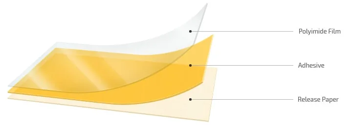
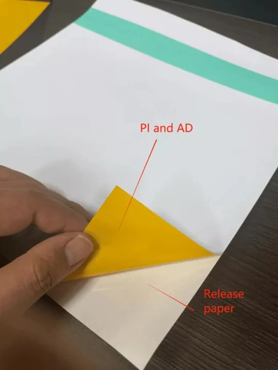
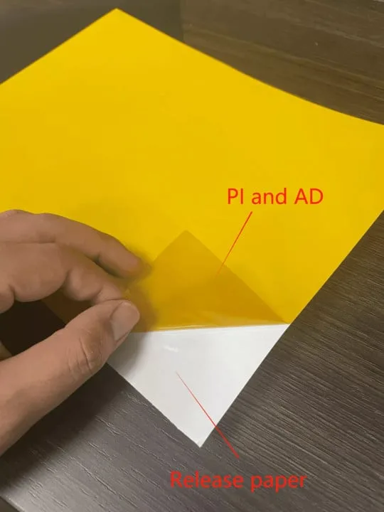
The flex PCB coverlay is composed of three parts: Polyimide (PI), Epoxy Adhesives (AD), and Release Paper. The utilized components comprise of PI and AD, while the release paper functions solely as a safeguarding adhesive that is required to be removed during practical application.

| Name | Polyimide Thickness μm (mil) | Adhesive Thickness μm (mil) |
|---|---|---|
| 13/15 | 13 (0.5) | 15 (0.6) |
| 13/25 | *13 (0.5) | 25 (1.0) |
| 25/25 | 25 (1.0) | 25 (1.0) |
| 25/35 | 25 (1.0) | 35 (1.4) |
| 25/50 | 25 (1.0) | *50 (1.0) |
Did you know that using Coverlay on your Flex PCB can offer a range of benefits for electronics manufacturers?
1. Protection of Copper Traces
For one, it can protect the copper traces on a FPCB from external elements like moisture, dust, and other contaminants that can cause electrical shorts or open circuits. The coverlay acts as a barrier between the copper traces and these elements, ensuring the FPCB remains functional and reliable over its lifetime.
2. Flexibility
Another advantage of Coverlay is its flexibility, making it ideal for use in FPCBs. Unlike rigid PCBs, FPCBs can be flexed or bent without breaking, making them perfect for applications where space is limited or where the PCB needs to conform to a non-flat surface.
3. Chemical Resistance
Furthermore, FPC Coverlay offers high chemical resistance to various elements, like solvents, acids, and bases. This feature makes it suitable for use in applications where the PCB is exposed to harsh chemicals, like in the automotive or aerospace industries.
4. Thermal Stability
Lastly, FPC Coverlay boasts excellent thermal stability, making it ideal for high-temperature applications. Polyimide films, in particular, have a remarkable thermal stability and can withstand temperatures up to 400°C without degradation.
While FPC coverlay provides numerous advantages, it also presents some difficulties that need to be addressed to ensure the best possible performance and dependability. These challenges include:
| Category | Characteristic | Advantage | Shortcoming |
|---|---|---|---|
| PI coverlay film | The same insulating base material as CCL is coated with heat curing adhesive: epoxy and acrylic adhesives are used. Open window for coverlay and heat cure after bonding with the substrate. | Convenient operation: High persistence, Excellent bending resistance. | Die laminating equipment shall be used for window opening; The bonding accuracy with CCL is difficult to control, and the adhesive overflow is difficult to control. |
| Photosensitive developing coverlay film (PI coverlay) | Paste the photosensitive coverlay film, form the window opening position through exposure → development, and then solidify. | The through-hole mask has good performance and can realize fine window opening. | Expensive price, poor bending performance. |
| UV heat curing ink | Screen leakage and solidification | No mold, low processing cost, and cheap materials. | It is difficult to open fine windows and poor bending performance. |
| Photosensitive ink | Through screen printing photosensitive resin, through exposure → development, the window opening position is formed and cured. | Forming a thin coverlay layer; The fine window opening can be realized; Cheap materials. | Easy to cause plug holes, poor bending performance. |
FPC coverlay is not the sole material option available to safeguard the copper traces on a flex PCB. Other options include solder mask and flexible solder resist. Solder mask, a liquid material, is cheaper than FPC coverlay but is not as flexible and does not provide an equivalent level of protection against environmental factors. Flexible solder resist, on the other hand, is akin to FPC coverlay in that it is a thin, flexible material that shields copper traces against external elements. It is more flexible than solder mask, but not as much as FPC coverlay and cannot offer comparable environmental protection.
The coverlay for sheet form materials such as plated through hole (PTH) and surface mount technology (SMT) incorporates various features using drilling, routing, laser cutting, knife cutting, or punch & die sets. The specific method(s) contemplated for manufacturing depend on the shape, size, and complexity of the desired features, as well as the quantity of parts.
These methods impose particular considerations beyond those of Flex LPI. For instance, larger minimum annular rings are necessary to meet exposed feature requirements. This permits material and manufacturing tolerances, as well as potential adhesive squeeze-out during lamination. Additionally, a larger minimum web thickness between adjacent features is required to prevent easily damaged thin sections and webs, and allow sufficient adhesive to guarantee proper lamination and circuit encapsulation. However, the coverlay for sheet form materials does not contain isolated “island” type features as they would fall out of the layer after machining.
In flexible PCB designs, if there are higher density SMT & PTH features, and the design allows for it, it is necessary to combine multiple feature openings into larger “ganged” openings to comply with the above requirements.

In some cases, rigid-flex PCBs with high density, complex designs, or specific component requirements may need both coverlay and LPI solder mask. These materials are selectively applied to certain areas of the board, and they offer distinct advantages when incorporated into a single design. To achieve full circuitry encapsulation without generating mechanical bend stress points in flexible areas, the PCB manufacturing files are designed to ensure that the two materials overlap within the rigidized zones. If these areas are neglected, the part’s reliability might be compromised. Although this approach increases production cost, it is often mandated by the rigid-flex design or deemed advantageous enough to justify the extra expenses. There are two common configurations of coverlay and LPI soldermask:
If your FPC and rigid-flex board designs incorporate the following materials, it may be necessary to apply coverlay in specific areas of the layers. The reason for this is that these materials may not adhere robustly enough to LPI soldermask and as such, they may not pass IPC quality control standards. Materials that may require coverlay include:
When designing Flexible Printed Circuit coverlay, there are several important design principles to consider. These principles include coverage, thickness, opening, anchoring, and traces. Proper attention to these elements is crucial to ensuring the performance and reliability of the flexible circuit. In this context, let’s explore each design principle in detail.
A. Coverage:
FPC Coverlay coverage refers to the extent to which the coverlay overlaps the conductor on the flexible circuit board. In general, the coverlay should completely cover the conductor, leaving only minimal or no exposed copper.
B. Thickness:
The thickness of the FPC Coverlay should be selected based on the specific requirements of the application. Generally, a thinner coverlay is preferred as it can help reduce signal interference and enable better bending of the flexible circuit.
C. Opening:
When designing FPC Coverlay, it is necessary to consider openings where components, connectors, or other features may be installed. Openings may also enable ventilation or facilitate the assembly process. The size and location of openings should be carefully considered to ensure proper functionality and durability of the flexible circuit.
D. Anchoring:
FPC Coverlay is typically anchored to the flexible circuit using adhesive or mechanical fasteners. The anchoring method used should provide sufficient retention force to maintain the coverlay in place during use.
E. Traces:
Traces on the FPC Coverlay are used to connect components on the flexible circuit. It is important to ensure that traces are properly aligned with the conductive traces on the flexible circuit board to avoid signal interference or other issues. Additionally, the width and spacing of the traces should be carefully selected based on the specific application requirements.
When you’re in the process of choosing the appropriate coverlay for your flexible printed circuit board, there are a number of crucial factors that need to be carefully weighed and considered.
By considering these factors in conjunction with your specific requirements, you can choose the appropriate Coverlay type and thickness to ensure that your flex PCB operates normally while bending.
FPC solder resist ink is a great alternative to the original coverlay film and performs the same functions. Its primary functions include:
Act as a surface insulator by being printed onto the copper foil circuit on the surface of the FPC, effectively isolating the contact between the copper foil and the external environment.
Provide a protective layer to prevent damage to the copper foil circuit during transportation and production.
Act as a barrier to prevent conductive foreign particles from falling onto the circuit, causing a short circuit.
The soldermask ink of an FPC circuit board also possesses other functions, such as being anti-plating, tin-resistant, and gold-resistant. It is also effective in providing a good soldermask role in SMT.
Hence, in summary, FPC board soldermask ink is essentially a protective paint layer that plays a significant role in providing an additional layer of protection to the FPC.
Some FPC coverlay manufacturers include Dupont, UBE Industry Co., Ltd., Kaneka, Japan, Mitsui Chemicals, Skckolonpi Korea, Damai Technology, Taiwan Dasheng Technology, Shengyi Technology Co., Ltd., and Tianjin Jiayi. These manufacturers have established a certain reputation and experience in the FPC industry.
Coverlay serves a similar purpose as solder mask by safeguarding the copper circuits, whereas a stiffener is designed to reinforce the endpoints of the pluggable flexible PCBs. Apart from PI, stiffeners made of stainless steel and FR4 are also available. While coverlay is indispensable for flexible PCBs and the flex portion of rigid-flex PCBs, stiffeners become necessary only when there are plugging requirements such as gold fingers.
Here's a detailed explanation of the manufacturing process for FPC Coverlay:
A. Material Preparation:
To begin with, the FPC Coverlay manufacturing process involves preparing the necessary materials. This includes selecting the appropriate type of material, such as polyimide or polyester film, and cutting the material to the correct size. Additional materials, such as adhesives or conductive inks, may also be prepared at this stage.
B. Coating:
After the materials have been prepared, the next step is to apply the coating. This involves carefully applying a thin layer of adhesive onto the surface of the film material using a specialized coating machine. The adhesive layer is typically only a few micrometers thick.
C. Drying:
Once the adhesive has been applied, the coated film is moved into a drying oven to remove any remaining solvent and solidify the adhesive. This ensures that the adhesive will properly bond to the underlying surfaces during the lamination process.
D. Laminating:
The final step in the FPC Coverlay manufacturing process is to laminate the coated film onto the FPC. This involves placing the film over the FPC and using heat and pressure to bond the two layers together. The laminating process must be carefully controlled to ensure that the adhesive properly bonds to the FPC surface without causing any damage to the underlying conductive traces or components.
A. Adequate Temperature Ramp-Up
One of the most common issues encountered during the FPC coverlay manufacturing process is inadequate ramp-up of temperature. This can cause the coverlay to not adhere properly to the substrate, leading to delamination and improper functionality of the final product. The temperature ramp-up should be performed gradually, ensuring that all layers of the material are heated uniformly and that no significant temperature differences exist between different areas of the coverlay.
B. Surface Flatness
Maintaining proper surface flatness is another critical concern when working with FPC coverlay. Any irregularities or bumps in the surface can lead to alignment issues during the lamination process, which can cause wrinkles or visible defects in the final product. It is important to ensure that the FPC coverlay's surface is as smooth and flat as possible before the lamination process begins.
C. Hole Accuracy
The precision of the holes or vias in the FPC coverlay is also a critical factor in determining the success of the manufacturing process. Properly sized vias must be created at the correct locations, and the holes must be precisely aligned with both the solder pads and the companion holes on the PCB. Any deviation from the desired specifications can lead to soldering problems, which can ultimately result in the failure of the final product.
D. Cutting Accuracy
Finally, the accuracy of the cutting or trimming process is another essential aspect of FPC coverlay manufacturing. The coverlay must be trimmed precisely to the correct size and shape, and any residual material must be removed carefully to avoid potential defects or long-term failures in the product. Any inaccuracies during this process can lead to poor adhesion, alignment difficulties, and other problems with the final product.
FPC Coverlay stands for "Flexible Printed Circuit Coverlay," which is a thin layer of protective material typically made of polyimide that is applied over a flexible circuit board to provide insulation and protection from environmental factors.
The purpose of FPC Coverlay is to protect the underlying flexible circuit board and its components from environmental factors such as moisture, dust, and debris, as well as to provide electrical insulation.
Polyimide is the most commonly used material for FPC Coverlay. Other materials such as epoxy and acrylic can also be used depending on specific applications.
Some benefits of using FPC Coverlay include improved protection against environmental factors, enhanced electrical insulation, and increased board stiffness.
FPC Coverlay is typically manufactured using a combination of thermal lamination and laser cutting technology.
Common issues include insufficient temperature during lamination, uneven surface finish, inaccurate perforation, and inaccurate cutting.
When you partner with us, we do everything to ensure your PCB manufacturing and assembly are completed on time to your specifications with the highest quality.
Fill out the form below, and we will get back to you within the next 24
hours to complete the order, and then you’re all set to get started!
Prefer to email? Feel free to contact us directly at sales@pcbjhy.com.