Rigid-flex PCBs have become increasingly popular due to their unique properties and versatility. Combining the flexibility of a flexible circuit with the durability and reliability of a rigid board allows these hybrid circuits to be used in a wide range of applications, from medical devices to aerospace systems. However, designing rigid-flex PCBs can be challenging, as it requires careful consideration of materials, layer stackup, trace width and spacing, and component placement. This blog post will discuss the key design guidelines and best practices for successful rigid-flex PCB design and potential challenges to watch out for.
What Are Rigid-Flex PCBs?
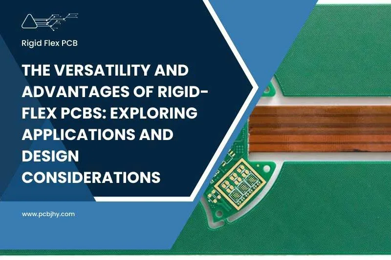
Rigid flex PCBs are a type of PCB that combines the properties of rigid and flexible circuits. They comprise multiple layers of flexible circuits attached to one or more rigid boards, creating a single circuit that can be folded or bent into a desired shape.

Benefits and Applications of Rigid-Flex PCBs
Rigid flex PCBs offer a range of benefits that make them an attractive option for a variety of industries and applications. By combining the properties of rigid and flexible circuits, rigid flex PCBs are able to provide a unique set of advantages, including increased design flexibility, improved reliability, and reduced space requirements. In this section, we will explore the benefits of using rigid flex PCBs in more detail, as well as provide real-life examples of their applications in various industries, including aerospace and defense, medical devices, consumer electronics, automotive, and industrial control systems. Whether you are a designer, engineer, or manufacturer, understanding the advantages and applications of rigid flex PCBs can help you make informed decisions about your circuit design and production.
Benefits of Rigid-Flex PCB
- Space-saving: Rigid flex PCBs can be bent or folded, allowing for more compact designs and reduced space requirements compared to traditional rigid boards.
- Improved reliability: The combination of flexible and rigid components can increase the durability and reliability of the circuit, as it can better withstand vibration, shock, and thermal stress.
- Reduced assembly time and cost: As rigid flex PCBs combine multiple components into a single circuit, there is often less assembly time required, which can result in cost savings.
- Increased design flexibility: The ability to fold or bend the circuit allows for more design options, enabling greater flexibility in creating custom shapes and sizes.
Applications of Rigid-Flex PCB
- Aerospace and defense: Rigid flex PCBs are commonly used in aerospace and defense applications due to their lightweight design, high reliability, and ability to withstand harsh environments. Examples include satellite communication systems and missile guidance systems.
- Medical devices: Rigid flex PCBs are used in various medical devices, such as pacemakers, hearing aids, and monitoring equipment, due to their ability to be molded to fit the shape of the body and withstand repeated use and sterilization.
- Consumer electronics: Rigid flex PCBs are used in various consumer electronics, such as smartphones, tablets, and wearables, to reduce size and improve reliability.
- Automotive: Rigid flex PCBs are used in various automotive applications, such as electronic control modules and infotainment systems, due to their ability to withstand extreme temperatures and vibrations.
- Industrial control systems: Rigid flex PCBs are used in various industrial control systems, such as robotics and automation systems, due to their ability to withstand harsh environments and reduce the size of the overall system.
Rigid-Flex PCB Design Guidelines
Designing a rigid flex PCB requires careful consideration of a range of factors, from materials selection to component placement and orientation. By following key design guidelines, designers and engineers can ensure that their rigid flex PCB meets the required specifications for their specific application. In this section, we will explore the most important design guidelines for rigid flex PCBs, including materials selection, layer stackup, trace width and spacing, drilling and vias, bend radius and angle, and component placement and orientation. Understanding and following these guidelines will help to ensure the successful design and manufacture of a high-quality rigid flex PCB that meets the unique requirements of your application. Whether you are a designer, engineer, or manufacturer, this section will provide you with the information you need to create reliable and durable rigid flex PCB designs.
- Materials selection: When selecting materials for a rigid flex PCB, it’s important to consider their ability to withstand repeated bending and flexing. Polyimide is a popular choice for flexible materials due to its high thermal stability, excellent dielectric properties, and resistance to moisture and chemicals. For rigid materials, FR-4 is commonly used for its mechanical strength, durability, and low cost. Copper is also a popular choice due to its excellent electrical conductivity.
- Layer stackup: The layer stackup of a rigid flex PCB should be carefully planned to ensure proper signal integrity and impedance control. The number and placement of layers will depend on the specific design requirements, but typically include a combination of rigid and flexible layers. The placement of layers should be designed to minimize signal loss and crosstalk, while ensuring the necessary mechanical flexibility.
- Trace width and spacing: The trace width and spacing of a rigid flex PCB should be designed to accommodate the specific electrical requirements of the circuit while also taking into consideration the manufacturing process. Narrow trace widths and tight spacing can increase the risk of manufacturing defects or signal degradation, so they should be carefully planned. Typically, trace widths of 5-6 mils and spacing of 6-7 mils are recommended.
- Drilling and vias: Drilling and vias are crucial components of a rigid flex PCB design, as they allow for connectivity between layers. The location and size of vias should be carefully planned to minimize any impact on the flexing portion of the circuit and to avoid any potential signal interference. Blind and buried vias are often used to minimize the impact on the flexible portion of the circuit.
- Bend radius and angle: The bend radius and angle of a rigid flex PCB should be designed to minimize stress on the flexible portion of the circuit. A smaller bend radius can increase the risk of cracking or tearing in the flexible material, while a larger bend radius can cause unwanted signal reflections or impedance variations. Generally, a minimum bend radius of 10 times the thickness of the thinnest layer is recommended.
- Component placement and orientation: Component placement and orientation should be carefully planned to ensure proper signal routing and mechanical stability. Components should be placed in areas of the circuit that will not be subjected to excessive stress or flexing, and their orientation should be optimized for signal integrity and ease of assembly. The use of surface-mount components is recommended for increased reliability and ease of assembly.
- By carefully following these design guidelines, designers and engineers can ensure the successful design and manufacture of a high-quality rigid flex PCB that meets the unique requirements of their application.
Challenges of Rigid-Flex PCB Design
When designing a rigid flex PCB, there are several potential challenges that designers and engineers may face. Some of the main challenges include:
- Manufacturing complexity: The manufacturing process for rigid flex PCBs is more complex than that for traditional rigid PCBs due to the combination of flexible and rigid materials. The manufacturing process involves several steps, including the creation of flexible circuits, the addition of rigid layers, and the lamination of the layers. This complexity can increase the risk of manufacturing defects and errors, which can impact the overall reliability and functionality of the circuit.
- Cost: Rigid flex PCBs can be more expensive to manufacture than traditional rigid PCBs due to the complexity of the manufacturing process and the cost of the materials used. The cost of materials such as polyimide and FR-4 can be higher than other materials used in traditional rigid PCBs, and the additional steps in the manufacturing process can add to the overall cost.
- Reliability: The use of flexible materials in a rigid flex PCB introduces an additional level of complexity and potential failure points. The repeated flexing of the circuit can cause stress on the materials and components, which can lead to cracking, tearing, or other failures. Additionally, the use of vias and other interconnects can also impact the reliability of the circuit.
- Testing: The testing process for rigid flex PCBs can be more complex than for traditional rigid PCBs due to the combination of flexible and rigid materials. Additional testing is required to ensure that the flexible portion of the circuit can withstand repeated bending and flexing without impacting the overall functionality of the circuit. This can add to the overall testing time and cost.
To mitigate these potential challenges, designers and engineers must carefully consider the specific requirements of their application and work closely with their manufacturing partners to ensure the successful design and manufacture of a high-quality rigid flex PCB. Close collaboration between the design and manufacturing teams can help to identify potential issues early in the process and develop strategies to address them effectively. Additionally, investing in testing and validation processes can help to ensure the reliability and functionality of the final product.
Best Practices for Rigid-Flex PCB Design
To ensure a successful rigid flex PCB design, there are several practical tips that designers and engineers should keep in mind:
Collaboration with manufacturer: Collaboration between the design team and the manufacturer is essential for a successful rigid flex PCB design. Working closely with the manufacturer can help designers to understand the specific manufacturing requirements and limitations, and to develop a design that is optimized for manufacturability. This collaboration can also help to identify potential issues early in the process and develop strategies to address them effectively.
Proper planning and communication: Proper planning and communication are critical for ensuring a successful rigid flex PCB design. Designers should carefully plan the layer stackup, trace widths and spacing, vias, and component placement to ensure proper signal integrity, impedance control, and mechanical stability. Additionally, clear and frequent communication between the design team and the manufacturer can help to ensure that everyone is on the same page and that potential issues are identified and addressed early in the process.
Simulation and testing: Simulation and testing are essential for verifying the performance and reliability of a rigid flex PCB design. Designers should use simulation tools to verify the electrical performance of the circuit and to identify potential issues with signal integrity and impedance control. Additionally, physical testing is essential for verifying the mechanical performance of the circuit and ensuring that it can withstand repeated bending and flexing without failure.
Careful selection of materials: The selection of materials is critical for the success of a rigid flex PCB design. Designers should carefully select materials based on their ability to withstand repeated bending and flexing, as well as their thermal and mechanical properties. The use of high-quality materials can help to ensure the reliability and longevity of the final product.
Proper documentation and version control: Proper documentation and version control are critical for ensuring the successful manufacture of a rigid flex PCB. Designers should maintain accurate documentation of the design process, including schematics, layer stackup diagrams, and manufacturing specifications. Additionally, version control is essential for ensuring that all members of the design team are working with the same version of the design, which can help to prevent errors and inconsistencies.
By following these practical tips, designers and engineers can help to ensure the successful design and manufacture of a high-quality rigid flex PCB that meets the specific requirements of their application.
Conclusion
In summary, rigid flex PCBs are a hybrid solution that combines the benefits of both rigid and flexible PCBs, allowing for greater design flexibility, improved reliability, and space savings. When designing rigid flex PCBs, careful consideration must be given to material selection, layer stackup, trace width and spacing, drilling and vias, bend radius and angle, and component placement and orientation. Challenges such as manufacturing complexity, cost, reliability, and testing should also be taken into account. To ensure a successful design, collaboration with the manufacturer, proper planning and communication, and simulation and testing are recommended. Overall, rigid flex PCBs are an excellent choice for a wide range of applications and should be considered by anyone looking to optimize their design for performance, reliability, and flexibility.
Your Trusted Rigid-Flex PCB Manufacturer in China
If you are looking for a reliable and experienced rigid flex PCB manufacturer, look no further. Our team has years of experience in the industry and can provide you with the support and services you need to bring your rigid flex PCB design to life. From material selection to layer stackup, from trace width and spacing to drilling and vias, we have the expertise to help you overcome any design challenges you may face. We are committed to providing you with the highest quality products and services, all while ensuring competitive pricing and timely delivery. Contact us today to learn more about our rigid flex PCB manufacturing services and how we can help you achieve your design goals.